Before you start, please note that I'm not an electrician and learned most of what I know by reading web pages, watching YouTube videos, forum posts, and bugging friends who actually are electrical engineers. Use any of my advice at your own risk.
Battery Box
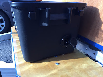
I didn't like trying to fit the battery and related components in the galley behind the galley module and after reading a few of the posts about the weight of the battery causing the galley flat to crack or delaminate, I decided to put the battery in the tongue box. I built a simple platform from some scrap plywood and mounted a plastic storage box to it. It isn't the prettiest thing but I wanted to get something up and running for the spring season. Hopefully I'll get time to either build a tongue box or buy a diamond plated one that matches the trailer fenders.Inside the box I mounted an all in one lithium ion battery from Chafon that provides 12v DC and 120v AC. There are a number of these all in one units available now, including some that wrap a lead-acid battery, but I liked this unit because:
- it is really light
- it has reasonable storage for the price (as far as Li-ion goes)
- it has all the charging and inverter components built in (and can be easily daisy chained or connected to solar panels)
- I can take it out and use it around the house when not on the road
On the side of the box I have an AC port plug to allow for charging the battery when power is available.
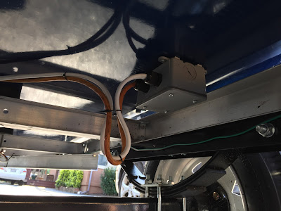
The supply lines then run under the length of the camper to just behind the galley bulkhead. I added a set of plugs just behind the tongue box so I can easily disconnect and remove the entire box to replace it or just to have an easy battery disconnect.
The lines enter the camper from the bottom by going through an exterior conduit box with two wire glands mounted on it. I originally wanted to put the wire glands directly on the floor of the camper but I couldn't find a reasonably priced solution that would span the 3/4" (or is it 7/8") thick floor because most wire glands are designed to mount to a sheet metal box. I did think about removing a small square in the floor and mounting some 1/4" plywood but then I worried about water proofing it and strength, etc. In the end, I used some weather stripping on the top of the conduit box and drilled a 1" hole through the box and the floor to bring the wires up.
The wires then come up through the floor just behind the galley bulkhead and run up and into the galley. The light strip shown there is an LED nightlight in a right angle channel that runs down either side of the bulkhead pointing toward the back of the camper. They are set to a nice blue color that provides a low level of light in the evening when the cabin lights are too much.
Galley Wiring
With the battery in the tongue box, I had a lot more room for wiring behind the galley module. I had an idea of the items I wanted/needed in the system and I didn't like the idea of mounting them all to the galley bulkhead. It's fairly thin material so wood screws need to be really small and I didn't want a bunch more bolts through the bulkhead. To provide a surface for mounting all my electrical components, I built a simple 4 sided box out of some scrap plywood and painted it to match the bottom of the camper (not that you'll ever see it).The box fits into the center compartment of the galley module and gives me 4 sacrificial plywood surfaces to mount to. The supply lines are coming in from the galley floor on the right side and running into the box. The lines run out to switch panels on either side and then to the final lights, fans, out outlets. I had to increase the notches on the galley module but everything tucks neatly out of sight.
Inside this box is where all the magic happens. Ok, not magic but a lot of wire connections. What's in the box:
- In the center is a 12v fuse box with 6 circuits.
- There are a number of screw terminals just to make splicing a little easier.
- On the left and right are LED RGB controllers that allow me to set a brightness and color for the LED cabin lights.
- In the center on the bottom are two latching relays to allow a 3-way switch like behavior for the cabin lights and night lights.
- On the bottom left is a junction box for the 120v line.
The lines run out of the central box and over to the back of switch plates on either side of the cabin, down through the galley floor for the night lights, through the bulkhead for the cabin lights, and, on one side, up to the galley lights. This is a little different from CLC's approach were they went up the bulkhead and directly through to the lights mounted in the cabin. I decided that I rather do the wiring run on the cabin side where I could hide it behind the headliner. The only wire really visible in the galley is the one line for lights.
A note of caution, I did put holes in the galley floor for the supply lines and the night light lines. In the event that I spill something in the galley, water will leak through these holes into the cabin. I use a rubber gasket and some caulk so fill the holes but anymore than an 1/8" of water and it will most likely leak. I'm willing to take that chance.
Inside the Cabin
Moving inside the cabin, the light and fan wires come in just above the shelf in the corner. I used some mesh wire sleeve to hide them a bit before they turn the corner to go up the wall behind the headliner.The front of the switch panel that was wired up from the galley side shows the switches and outlets I selected. I couldn't find a panel I liked so made one by cutting it out of 1/4" plywood and staining it a contrasting color. There is a separate panel on each side of the cabin. The panel includes:
- 120v outlet
- 2 x 12v barrel outlet, one with a USB charging insert
- 2 x on/off toggles for a personal fan and reading light
- 2 x momentary toggles for the cabin lights and night lights
- An LED indicator light for 120v power
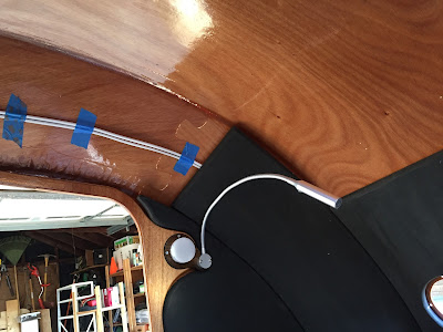
The wiring continues up the wall, then splits off in two directions. The first two lines go to the main cabin lights on the bulkhead and the personal fan. The second two lines go to the secondary cabin light and a personal reading light. I used 16 AWG wire for most of this which was probably overkill but I was worried about voltage drop over these distances. I'd probably go with 18 or 20 if I did it again because the LED lights don't seem to be affected by a slight voltage drop over 10 feet. The 16 gauge did fit behind the headliner but it shows a little bulge in places.
As to the lighting, I wasn't happy with a lot of the options I could find. They were either ugly, not bright enough, too blindingly bright, or the wrong color temperature. After ordering a few products and returning them, I finally decided to make them myself. Again, I cut a mounting panel out of 1/4" plywood, stained it, and mounted 4 strips of LEDs to it. I used a piece of 32% translucent acrylic to diffuse the light. The panel also serves to mount the personal fan next to the light.
For the reading light, I again cut a custom 1/4" plywood panel and mounted both a small under cabinet light and a gooseneck reading light. The under cabinet light is on the same switch as the main cabin light so you get both front and side lighting. I used a small circle of the same acrylic to diffuse these lights as well. The reading light is on a separate switch per side. The reading lights have their own built in dimmer and switch but they remember their state when toggled via the panel switch which is an issue I ran into with some cheaper lights.
I ran the wires down the center of the panel rather than against the door so the headliner could grab on either side of the wires to keep everything in place. Again, this might not be an issue with 20 gauge wire.
Once the headliner was in place and things were buttoned up, the wiring wasn't really noticeable at all. The wiring, panels, and lights are a mirror image on both sides of the cabin with the exception of an additional wire running all the way up to the top vent fan on one side. With the control panels on either side of the cabin 1) you can easily reach them while standing outside the door and 2) there is a large empty area in the center of the bulkhead for a tablet or other entertainment.
Finishing up the Galley
With all the wiring in place, I installed the galley module which has its own switch panel. Again, a custom panel but left natural to contrast the module face frame.This panel includes:
- 2 x 120v outlets
- 2 x 12v outlets
- 1 on/off switch for the galley lights
I can still access the wiring box in the module hatch for a quick repair without having to remove the entire galley module but anything more than tightening a screw will probably be a little challenging.
Final Thoughts
Overall I'm happy with how it all turned out. I like having the battery in the tongue box for easy access at the cost of some storage space. I saw that some other builders mounted the battery underneath the cabin which is also a good idea. I also like how there is almost no wiring visible other than the few inches from the bulkhead to the headliner.I hope this gives you some ideas and I'll post updates after I get some more time using the configuration in the great outdoors!


